HOW CAN A WING WORK BETTER?
There are a lot of very clever innovations that can make a wing generate more lift. Nicholas Heath learns the ups and downs of the subject with some scientific help from James Heath and Pat Larcey.
The Shape of the Thing
Do you remember having to look at this little fellow at some stage of your training?
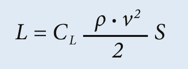
It’s the recipe for lift.
It says that lift = coefficient of lift x (density x velocity squared over two) x wing area (surface).
Wing area is an obvious one. And multiplying the thickness (density) of the air and your speed through it would appear to be straightforward in having an effect on lift. But what is this lift coefficient and what does it do?
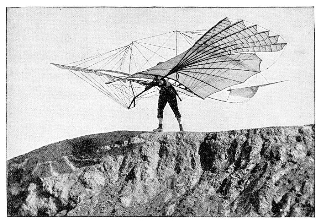
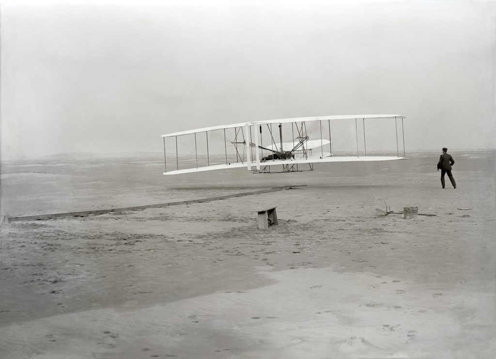
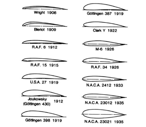
The thing that determines the lift coefficient is the shape of the wing. This shape can be broken down into the chord – how long it is from front to back – and the thickness or camber of the wing. But that’s not the whole story. The shape of the wing – the aerofoil – also has a lot to do with it. Aerofoil design goes back to the birth of aviation. The Wright brothers spent a lot of time trying to develop an aerofoil shape that would give them the most lift. They based much of their design on the pioneering work of glider pioneer, Otto Lilienthal. Things got a lot more scientific when the National Advisory Committee for Aeronautics (NACA) in the US started to research aerofoil shapes in detail during the 1920s. They came up with a number of aerofoil shapes that are still in use today. Most of their early work was focussed on aircraft that flew in the speed ranges we, as RAAus pilots, fly in. Many of the aircraft we fly still use aerofoil shapes based on those developed by the NACA almost a century ago. If you’ve ever flown a Tecnam, chances are you were under an NACA63A aerofoil. In most Cessna 172 or 152, it’s a NACA2412. For Jabiru it’s the NACA4412. And so on.
It turns out this coefficient of lift isn’t something you can work out with a formula. It’s done experimentally. Take our friendly lift formula, plug all the other numbers in and the missing bit – the coefficient of lift – will reveal itself. So, the coefficient of lift is the x-factor. The number we put in to explain how it came out the way it did.
Now let’s start an argument. We will do that by talking about what causes lift. Every time we talk about this in SportPilot we receive several letters, mostly in capital letters with flecks of spittle still on them from quite angry readers. You can see where the crayon snapped and tore the page. We love enthusiastic feedback like that. So here we go…
There’s a reasonable agreement that lift is caused by lower pressure above the wing than below it. Steps back and nervously scans the room. Whether the lift is caused by pushing from the bottom or pulling from the top is the sort of discussion that leads to brawls and breaks up families. Let’s just accept that it happens. We know this, because we fly. As to why there is less pressure above the wing than below, the traditional school of thought is the the path-length effect (Bernoulli). Basically, the Bernoulli effect suggests that if the path around the top of the wing is longer than the path around the bottom, the air will have to travel faster to make the journey and will be more spread out, resulting in less of it. A classic aerofoil achieves this by having the long, cambered surface above it. The problem with that is it doesn’t quite bear up to measurement. The air can be demonstrated to be moving faster than the extra distance would warrant. Fortunately for us, this effect doesn’t matter too much in the speed ranges we operate in. So we will stick to Bernoulli and Netwon’s laws for now. If you’d like to know just how complex the subject can get, have a look at this article in Scientific American (www.scientificamerican.com/article/no-one-can-explainwhy-planes-stay-in-the-air/). Feel free to submit your thoughts to us. Regardless of what you might think is causing it, what we do know from physical experiments is what various aerofoil shapes will do.
For most of us flying RAAus category aircraft, our wing aerofoil and shape will be fairly simple. A simple wing is cheaper and easier to construct and it serves our purpose well at the airspeeds we operate at. The classic “Hershey bar” (named after the chocolate bar) wing of the Piper Cherokee is a good example: a rectangular wing plan of constant chord and aerofoil shape. In theory, the most efficient wing plan (when viewed from above) is the elliptical wing, made famous by the Supermarine Spitfire of WW2. Also, by many birds. So why don’t we use elliptical wings? Simple. They are complex and difficult to build. It was a major issue for the Spitfire that made it hard to upscale in production. Birds required 165 million years of evolution. For most home-builders, that’s going to push the project timeline way out. For our purposes we will keep it simple.
Let’s look at some common aerofoil shapes and what they do. Apologies to many of you who already know about this, but trust me, we will be back to fight club before long.
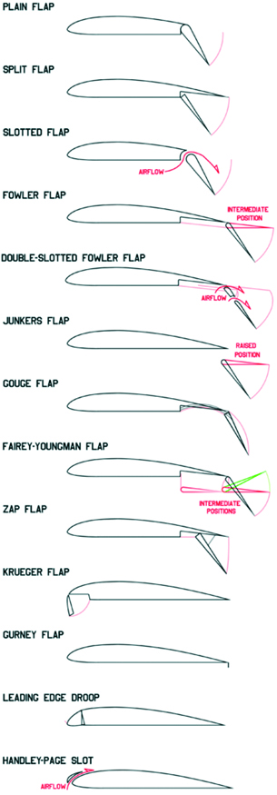
In general, fatter aerofoils will give you more lift for a given area and a lower stall speed. The trade-off will be speed and economic cruising caused by greater drag. A thin aerofoil will give you more speed and economy – at the cost of a higher stall speed and lift.
That seems simple enough, doesn’t it? Fat wings for good low-speed characteristics and thin wings for speed. But what if you wanted the best of both worlds? Rest assured, you’re not the first person to ask that question. Welcome to the wonderful world of lift aids.
The most common lift aid we use are flaps. The deflecting flap appeared first at Britain’s Royal Aircraft Factory in 1914. It didn’t gain popularity at first. But as aircraft speeds and weight increased, the benefits of the flap became obvious. The flap can give us lower stall speeds, a better angle of attack and increased drag. Yes, in this case increased drag can be a good thing – especially if you are trying to slow an aircraft down for landing. The increased angle of attack allows the aircraft to make a lower nosed approach, much better for keeping that runway in sight.
There are more types of flap than there were ways Bubba told Forrest Gump to cook shrimp. The most common one you will see is the Plain Flap. Bit of a giveaway in the name, really.
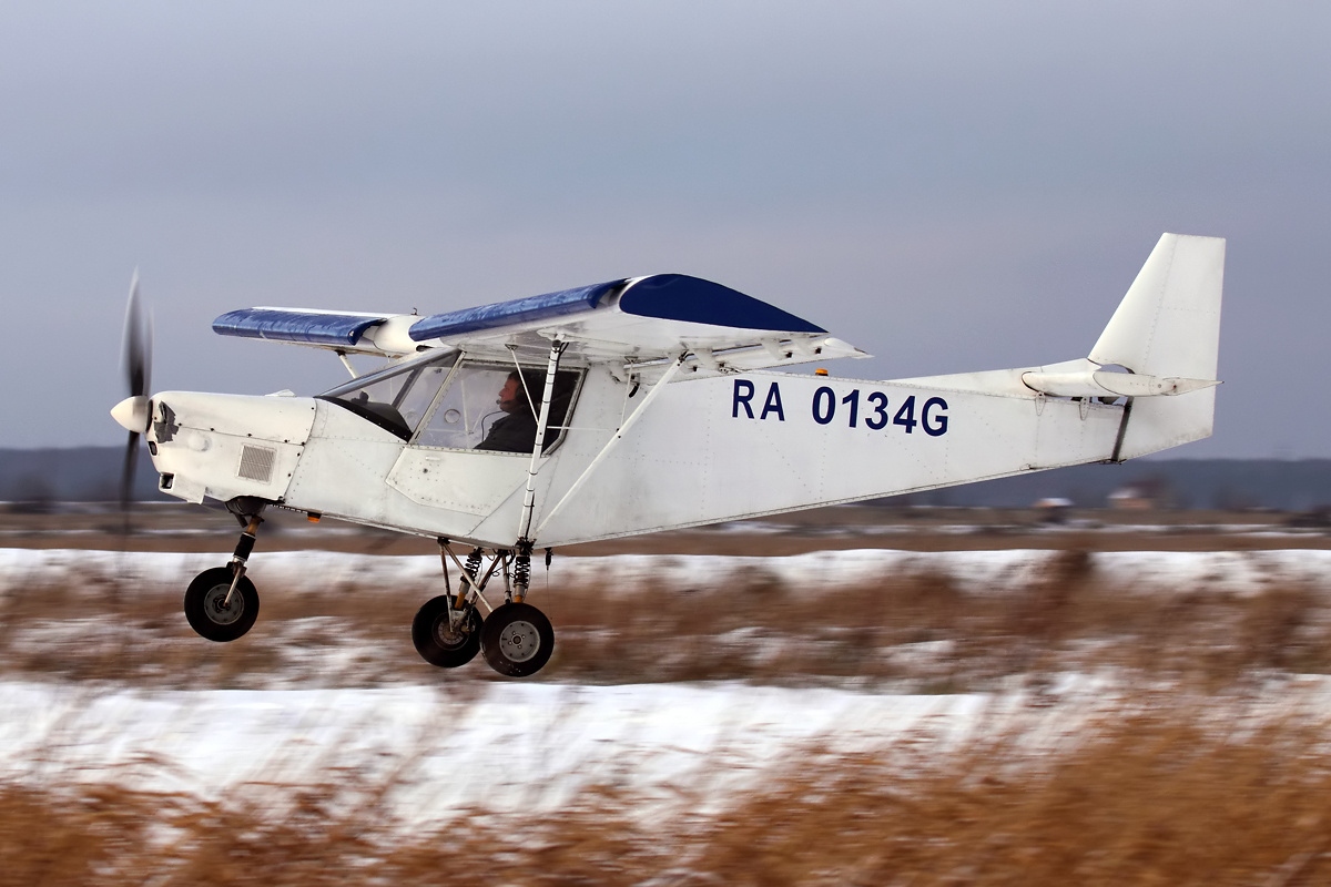
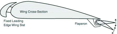
The other less common lift aid you will see, particularly on STOL aircraft, are leading edge slots and slats. The slot is a gap at the front of the wing. The slat is the device that makes the slot. Probably best to look at the picture about now. This creation of an almost mini wing at the front of the main wing helps to keep the airflow attached to the wing and delay stall. First developed by Handley Page aircraft in the UK (those Brits again), slots can improve the lift coefficient by as much as 40-60% and increase the stall angle from a typical 15 degrees to perhaps 20 to 25 degrees. Just to complicate matters, you can also use the slot effect on flaps for even better low and slow performance.
There are a couple of other wing enhancements you will commonly see on RAAus class aircraft, which we will cover briefly. The first relates to safe stalling. In an ideal world, a wing should stall at the inner section first. If a wingtip stalls on one side you will have a fairly aggressive roll occur. If it stalls at the root end, you will get a much more benign effect. This can be achieved with a few methods. One is to add wash-out to the wing tips. In effect, the wing has reduced angle of attack at the tips, thus ensuring that the root end stalls before the tip. Remember our Cherokee wing? Where you have the flat, straight Hershey-bar-type constant chord and profile wing, the addition of small stall strips on the leading edge for the inner section for the wing will cause that section to stall earlier than the tip. That’s why Piper aircraft fitted with stall strips tend to mush, rather than violently stall and spin. The other item you will often see are wing tips. The primary function of a wing tip is to reduce drag. Some designs also reduce spanwise air movement, which theoretically helps with lift. Similarly, some aircraft have fences to stop air moving toward the tip.
Which wing shape, size and lift aids you use ultimately comes down to your mission and budget. A modern jetliner wing has the ability to transition from low and slow flight to near supersonic. It does this using every piece of lift technology available and costs tens of millions per wing. For us mere mortals, where price and ongoing maintenance are key issues, a designer will choose the best wing profile for the speed range they wish to optimise.
Flaps are the next cheapest and simplest lift aid. Only STOL aircraft will consider complexities such as slots and slats. As a pilot, we need to be able to look at the wing of an aircraft and understand what it is designed for. Hopefully this article has added to that understanding.
Let us know what you think matters on a wing design via editor@sportpilot.net.au