Computational Fluid Dynamics (CFD)
uses computers to model fluid flow over surfaces (such as air over a wing) using equations such as Navier-Stokes and Euler. The massive increase in computer power since CFD started means that now we can model lift, drag and pressure over an entire aircraft with millimetre precision. For Fluid Dynamicists, there is no mystery about how a wing generates lift— it’s all perfectly explained by the equations.
However, pilots need a more intuitive understanding of how their aircraft interacts with the air and how their control inputs change that interaction. As a result, we use simplifications, metaphors and (unfortunately) myths. The purpose of this article is to debunk the Bernoulli myth and to provide two useful mental models for lift; one simple “big picture” view, and one more complex two-surface view.
BUSTING BERNOULLI
When I studied fluid dynamics as part of my engineering degree, we were taught that Bernoulli’s principle applies to an incompressible fluid flowing through an enclosed duct, where a constriction in the duct (a venturi) causes a higher velocity (to preserve overall flow rate) and therefore a lower pressure. The major flaw with the Bernoulli theory of lift is that the wing is not an enclosed duct.
Proponents of Bernoulli lift say “the higher air speed above the wing causes lower pressure”, but they have it backwards. There is only one thing besides gravity that can cause a fluid to accelerate; a difference in pressure. Air flows from high pressure to low pressure, so the air speed is higher BECAUSE the pressure is lower above the wing. Similarly, the air below the wing slows because the pressure is higher.
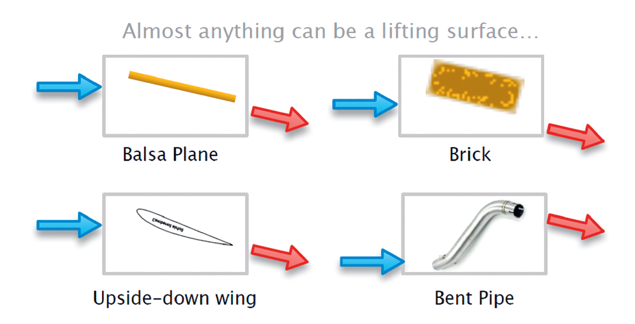
Finally, the curved upper surface doesn’t cause the lift— otherwise why can aircraft fly upside down, or flat surfaces like balsa planes or paper planes provide lift?
Let’s start with the simple explanation; flow turning.
THE BIG PICTURE: FLOW TURNING
NASA has written many articles about lift, including one a couple of years ago that describes how flow turning generates lift [1]. The idea is that when airflow is redirected, Newton’s second law (F = ma) says force is needed to accelerate the air, and the third law says that an equal and opposite force (lift and drag) is generated. Any shape can be a lifting surface if it redirects airflow, even a bent pipe.
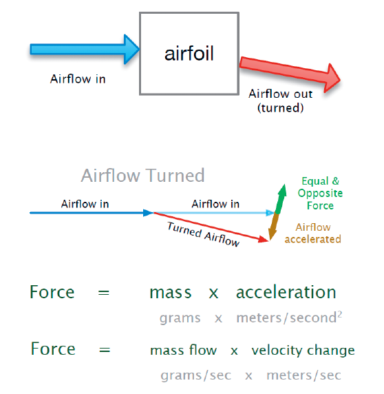
The force is proportional to the mass flow (grams per second turned) and velocity change (metres per second). Higher speed and higher angle of attack give more mass flow so more lift. You already have an intuitive understanding of this from sticking your hand out the car window; higher speed gives more effect, as does changing the angle of your hand.
This model gives a good intuitive understanding of lift, but if you want to go deeper, we have to look at how the air interacts with the wing.
THE TWO-SURFACE MODEL
Doug McLean, a Boeing Technical Fellow, wrote a book “Understanding Aerodynamics: Arguing from the Real Physics” [2] that uses physics to explain lift (among other things) and debunks many myths. He has since revised his explanations to better explain the interconnected nature of flow turning, lift, drag and high/low pressure. One of his fundamental concepts is that both the upper and lower surfaces of the wing generate lift, but in totally different ways. Let’s look at those, using my radical simplifications of Doug McLean’s physics.
UNDER THE WING
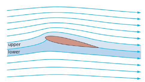
This one is relatively simple; it’s just flow turning. As the bottom surface of the wing hits the air (or the air hits the bottom), the air is accelerated downwards and slightly forwards, generating higher pressure, lift and drag. Newton’s second law and third law in practice. You can refer to the diagrams above.
OVER THE WING
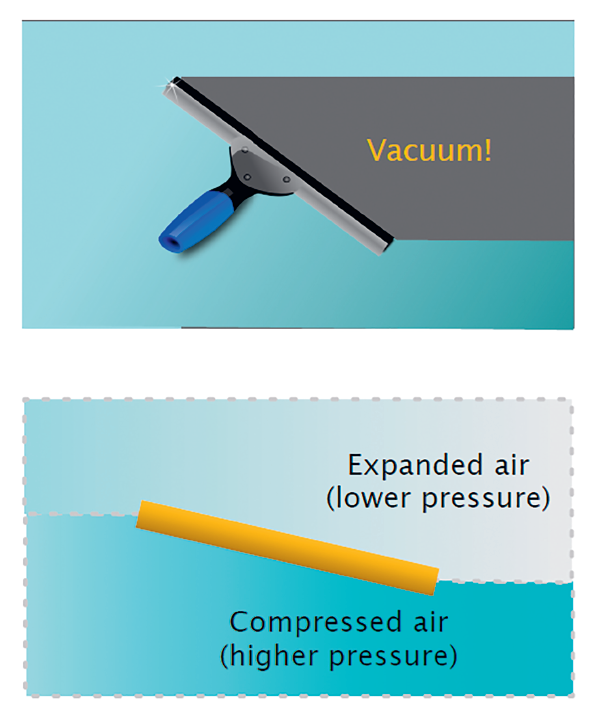
This one is way more complicated. To avoid the distraction of the curvature, we’ll think of a balsa plane’s flat wing, with a small angle of attack. It is a bit like an angled squeegee going across a wet window: the water below the squeegee (and the air below the wing) is pushed downwards, leaving a gap above the squeegee. If air was like the water on the window, there would be a vacuum above the wing. But air abhors a vacuum, and it rushes into the gap. If you imagine the amount of mass in the disturbed air a certain distance above the front of the wing, this mass is in a larger volume at the rear of the wing, so the pressure above the wing is lower than ambient pressure. Lower pressure above the wing means lift.
But it doesn’t stop there. We’ve already seen that air accelerates from high pressure to low pressure, so the air rushing in to fill the gap is accelerated down and backwards. By the time it gets to the trailing edge, it is going faster than the incoming airflow, and heading downwards by at least the angle of attack, or more with a curved wing. You can work out the lift from the flow turning.
But wait, there’s more! Because the uppersurface airflow is angled down, it helps stop the lower-surface airflow from wrapping around the trailing edge, so the upper airflow not only generates its own flow turning, it helps preserve the flow turning of the lower surface.
So why is the upper surface of a wing curved? Well, some aren’t at all— such as a paper plane or balsa plane. Some aren’t curved much. Some aerobatic aircraft have symmetrical wings. But most have more curve at the top than the bottom — they are cambered. The simple explanation is that the top curve better matches the curved path of the accelerating air over the wing, guiding it and maintaining smooth flow across the surface, avoiding drag-inducing turbulence. That’s why STOL wings are fat and curved, while high speed wings are much flatter.
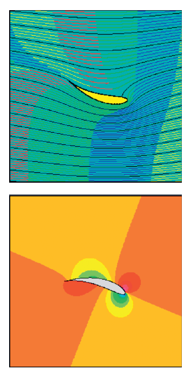
The University of Genoa have done some really cool CFD animations [3] that show how the air is accelerated and turned downwards, and how pressure above and below the wing change with positive and negative angles of attack. I’ve hosted a copy of some of these [4] so you can see the animations without downloading them.
To sum up; lift and induced drag are generated by two different types of flow turning above and below the wing. The upper curve helps guide the flow for more lift and less drag. No need to call on the Bernoulli equations!
Thomas Bisshop is an RA-Aus Instructor, carrying on a family tradition of fascination with the physics of flight.